Multigraphs in Chemistry

Today we are going to talk about multigraphs and apply them to chemistry.  A multigraph is just a graph in which multiple edges and loops are allowed.  Multiple edges are the name for having more than one edge between two vertices, and loops are edges both of whose ends are at the same vertex.  It turns out we can once again represent Lewis structures like this.  A lone pair is a loop, a double bond is two edges, and a triple bond is three edges.

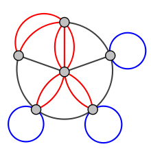
Above is a multigraph, courtesy of the great Wikipedia:  http://upload.wikimedia.org/wikipedia/commons/thumb/c/c9/Multi-pseudograph.svg/220px-Multi-pseudograph.svg.png.

Note that you have the red multiple edges and the blue loops.

So what are the properties of a mutigraph we are concerned with?  Once again we have vertices, edges, and degree.  The vertices are the gray dots in the above diagram, and the edges are the black, red, and blue in the diagram.  Degree is defined to be the number of edges adjacent to a vertex, where loops are counted twice, one for each end.  In this way the sum of all degrees is still twice the number of vertices.

This is nice.  For starters we can represent any Lewis structure much more completely with this convention.  Graph theoretic properties once again have interesting meanings.  Every edge still represents an electron pair.  The degree of a vertex still represents the number of electrons in its valence shell after bonding, where loops are counted twice for a vertex.  Formal charge has an interesting representation now.  It is the difference between the number of electrons present on the individual atom and the degree in the accompanying graph.

Pictures might be an excellent aid, but it’s better to construct lewis structures yourself!  Draw the Lewis dot structure of your favorite compound, say glucose.  Go on now.  Do it on paper.  Start by making a graph with the atoms as vertices.  Now, turn the lone pairs into loops, so for every lone pair, drawn an edge from that lone pair’s atom to itself.  Finally, draw an edge between two atoms with a single bond, draw two between two with a double bond, and draw three between two with a triple bond.  There you go.

Now, once again these multigraphs can be applied to calculate the formula of certain compounds!  Let’s start with hydrocarbons because they are simple.  Say we have an acyclic hydrocarbon with 5 carbons and 8 hydrogens.  What bonds can it have?

Note that this is an alkane so there are no cycles.  There are also no lone pairs because carbon is not very electronegative and instead makes 4 bonds.  The carbons in total have degree 20 because they need to be adjacent to 4 edges (electron pairs).  Since 8 of these are taken up by carbon-carbon sigma bonds (there are 4, because of our tree with 4 edges, but each is counted twice for each of the carbons), and 8 by C-H bonds, C-C pi bonds are counted a total of 4 times, which means that there are 2 of them.  So either there is a triple bond or two double bounds.

Let’s do another example.  What does carbon monoxide look like?  First, we can draw the simple graph for it, which is a carbon connected to an oxygen.  The edges in the simple graph represent the sigma bonds that do not hold lone pairs, and onto them we will draw the extra multiple edges which represent pi bonds.  Clearly 5 edges need to be drawn in some capacity, since we need 10 total valence electrons.  4 are for the carbon, and 6 for the oxygen.  The only way to do this is to make two extra pi bonds between C and O and then give each of C,O a lone pair.  So we have a graph on two vertices connected by a triple edge, each of which has a loop attached to it.

So we have seen that the idea of interpreting Lewis structures as simple graphs can be extended to interpreting them as multiple graphs.  Once again, this allows us to mathematically capture the structure of many compounds and rationalize their structures to some extent using degree arguments.  Once again, there is still nothing about the actual shape of the molecules involved here, but that is covered very nicely in our previous posts on Group Theory.  Stay tuned for next time!

Different OLED Variants

In a market where consumers demand innovation and novelty products with each passing quarter, some ideas flop while others soar to unimaginable amounts of profit. The technology industry is commanded by the need to satisfy the ever changing needs of the techno-savvy community. Right now, exploration into OLED’s has taken the big name corporations by storm, as they consider the plethora of different paths they can take with such an applicable concept. Whether it be in the lighting, cellular phone, or television, OLED’s are sure to make it into the homes of Americans soon. Yes, OLEDS are the next big thing.

AMOLED

Although not prominently advertised as OLED displays, there are multiple variants of OLEDs that have been in the market for many years. One of those is AMOLED, the active-matrix organic light emitting diode, often seen specifically in the smartphones that several Americans have today.  It is also present in televisions and its market is perfect for affordable and efficient devices.

The AMOLED holds the active matrix, which generates the light the thin-film transistor (TFT) array is electrically activated.  In an AMOLED, the TFT serves as a series of switches that controls the current flowing to each pixel.  As its name suggests, TFT is a field-effect transistor that deposits thin films on an active semiconductive layer onto a substrate usually made of glass. Commonly made from silicon, the characteristics of a silicon-TFT are dependent on the crystal structure of the silicon.  As previously mentioned the TFT layer can be composed of indium tin dioxide to create a transparent semiconductor for use in displays such as OLED and AMOLED.  The TFT array plays a significant role in AMOLED function due to its duality.  The continuous current to a pixel is controlled simultaneously by two TFTs.  One TFT starts the charging of the storage capacitor while the other provides a voltage that maintains a constant current.  This process allows for a lower required current to run, making the AMOLED more ideal in smartphone use.

The integration of TFTs is fundamental to the function of AMOLED displays.  The two main TFT technologies in commercial use are polycrystalline silicon (poly-Si) and amorphous silicon (a-Si).  Amorphous silicon does not contain the normal long range order of a tetrahedrally bounded silicon atom.  Thus, it can be passivated by hydrogen which allows a-Si to be deposited in low temperatures.  On the other hand, polycrystalline silicon is composed of a homogenous crystalline framework.  The entire layer is continuous and deposited easily onto a semiconductor wafer.  In the end, both methods allow the active-matrix backplanes to be fabricated in low temperatures for flexible AMOLED displays.  Further information on TFT displays can be found here.

Figure 1: Different variants of TFT layers used for various applications


AMOLED displays and phones were most commonly developed by Samsung and Motorola.  Like all technologies, there are various variations within the AMOLED family as well.  Samsung has incorporated the AMOLED displays into their Galaxy S range quite extensively, as the powerful Samsung Galaxy Note 3 was fitted with a Super AMOLED screen.  The Super AMOLED Plus was later introduced with the Samsung Galaxy S II.  It is an improvement from the Super AMOLED screen by replacing the PenTile 2 subpixel RGBG matrix with the three subpixel RGB RGB matrix. Upgrading from a two subpixel RGBG matrix with the three subpixel RGB RGB matrix allows for a crisper image, and cleaner, smoother looking text.  This replacement made the screen much brighter and energy efficient than its predecessor while giving a clearer picture due to the increase in subpixels.  The HD Super AMOLED would then follow in the Samsung Galaxy Note.  Although the Galaxy S III uses a 2 subpixel RGBG matrix HD Super AMOLED, the screen was upgraded for the Galaxy Note II by using a 3 subpixel RBG matrix.  The Samsung Galaxy Round also uses the AMOLED screen, as a part of the curved phone fad that has started to hit the market.  This screen, the Super Flexible AMOLED capacitive touchscreen is paramount curved handsets, since it is able to be made transparent and flexible, which is required for a phone that wants to achieve wider viewing angles through bending screens.

Figure 2: Samsung Galaxy phones using an AMOLED display


PMOLED

       OLEDs can also be made using passive-matrix addressing schemes.  PMOLEDs are fundamentally the opposite from an AMOLED.  They were used in early displays and are not commonly seen anymore.  They function by controlling each line of pixels sequentially without the use of a capacitor.  The lack of a capacitor makes PMOLEDs different from AMOLEDs in that they do not use a TFT layer to keep the pixels constantly on.  This results in most of the pixels being off for the majority of the time.  To adjust for this, more voltage is required for brightness.  Although this principle makes PMOLEDs easy to manufacture, the quality and lifetime of PMOLEDs are severely lower than AMOLEDs.  The fact that they require more voltage for each line of pixels also restricts the size of PMOLED displays.


Figure 3: Transparent TDK PMOLED screens

Conclusion

       Although PMOLED displays were a good foray for many companies when the OLED market was still in its infancy, it is now clear that they are less desirable than AMOLED displays.  By using the technology similar to old CRT displays, PMOLED pixels were controlled by switching on a row and a column.  The intersection of the row and column was then lit up.  Although they were easy to build, the restrictions in size severely limited PMOLED applications.  They also consumed power at a higher rate.  On the other hand, AMOLEDs used a unique principle where each pixel is controlled individually.  This allows for larger displays and power efficiency at the cost of ease of production.  Thus, as the full capabilities of PMOLED and AMOLEDs were discovered, each fit into their own niche market.  PMOLEDs are now integrated more in small MP3 players while AMOLEDs dominate the smartphone market.

Evonik’s ULTRASIL Tires increase fuel efficiency

Company Profile:

Evonik Industries is one the world’s lead specialty chemical companies. One of the main goals of the company is to provide product that solve problems and provide a maximum benefit to customers and society. Recently, they have developed a more fuel efficient tire that does not compromise on performance through the implementation of a silica-silane system, known as ULTRASIL.

ULTRASIL:

The greenhouse effect is a natural process in which radiant heat from the sun is captured in the lower half of the atmosphere, directly resulting in higher temperatures and thus global warming. In order to reduce this greenhouse effect, most companies are working towards minimizing carbon dioxide emissions from transportation. Carbon emissions from combustion of energy fuels has accounted for 81.5% of total greenhouse gas emissions over the last several years, and global warming is quickly becoming a major problem throughout the world. Transportation contributes to this on a large scale, and it is responsible for 31% of the CO2 emissions from the United States. However, Evonik’s silica-silane system (ULTRASIL) is a unique approach to this problem. ULTRASIL is created in several different forms and is applicable in many different situations, however its primary purpose is to serve as a coating for tires. This advanced tire technology can reduce the rolling resistance of tires, increase traction in wet conditions, and reduce carbon dioxide emissions. In general, tires have been targeted as quick way to reduce carbon dioxide emissions, as simple changes in size and shape can increase fuel efficiency by up to 15%.

ULTRASIL is able to reduce rolling resistance between tires and wet or icy road conditions due to the presence of intermolecular forces (IMFs), which can determine whether a solid will be hydrophobic (resists water) or hydrophilic (attracts water). This is an important concept to the concept of ULTRASIL because it is produced with hydrophobicity in mind. Being hydrophobic, water will adhere to the ULTRASIL coated tires, resulting in increased traction between the tires and the road. The major types of intermolecular forces that impact hydrophobicity include dipole-dipole forces, hydrogen bonding, ionic interactions, and London dispersion forces.

Dipole-dipole forces, hydrogen bonding, and ionic interactions are all known to be hydrophilic interactions. The larger presence of these forces in a molecule, the more the solid will attract water molecules. Dipole moments in a molecule are dictated by the polarity of a molecule. Polarity is the sum of all of the bond polarities in a molecule, resulting in dipole moments. The dipole moment is measured in a vector as the sum of the individual vector movements. For example, CO2, a linear and non-polar molecule, has no dipole moment. Hydrogen bonds are the interactions of a hydrogen atom with a nitrogen, oxygen, or fluorine atom. They are a much more powerful force than dipole-dipole forces, resulting in a larger increase on the hydrophilicity of the molecule. Similarly, the presence of ionic bonds (interactions between positive and negative ions) can have the same effect.

London dispersion forces, the weakest of the intermolecular forces, are the sole forces that can raise the hydrophobicity of a molecule. This force, also called an induced dipole-dipole force, is a temporary attractive force that results when the electrons in two adjacent positions occupy positions that make the atoms form temporary dipoles. These forces occur in all molecules. In the production of ULTRASIL, Evonik has created a silica-silane system, where the hydrophobic regions of the molecule dominate, causing adhesive forces to arise and increase the tension between tires and wet/icy road conditions. More information about intermolecular forces can be found here, or

.

Also, the chemical structures of the silica helps contribute to its unique properties. Silicon dioxide can exhibit one of the largest varieties of crystal structures among the compounds commonly available and used. These many different crystalline forms allow silica to be used in a broad range of applications, including ULTRASIL. Precipitated silica, which is key to this product’s functionality, is a specially prepared form that has an amorphous structure, similar to silica gel or glass, both of which are predominantly silicon dioxide, or silica. As already discussed, adding these silicon dioxide granules to the surface of rubber tires has many beneficial effects on vehicle performance, but binding this hydrophilic molecular solid to the long, continuous, and hydrophobic polymer chains that make up vulcanized rubber can be difficult. It is up to sulfur, linking the polymers of vulcanized rubber to make it more resistant to temperature extremes, to act as a coupling agent for silica, since the hydrocarbon polymers will not bond to it by themselves.

From what we know, however, ULTRASIL production takes a rather different approach to solving the problem of coupling silica to rubber: the silica-silane system. By treating the original rubber  material with various organosilanes, a surface that silica particles can easily bond to is created, making it possible to form the desired composite with more cross-links to the silica granules and a higher overall thermal stability than without the treatment. Organosilanes usually have both a nonpolar and polar end and can not only bond with vulcanized rubber, but also with the silicon dioxide particles, through dehydration synthesis of their hydroxyl groups with the hydroxyl groups that cover the surface of the silica particles.

While many of the specific details of the ULTRASIL manufacturing process are trade secrets of Evonik, the company does share the basic concept of how it obtains the very pure amorphous silica needed for its products: precipitation from solution. Precipitated silica is widely used in industrial processes around the world, and Evonik Industries is its largest producer. Just like in ULTRASIL, these fine silica grains are often used in rubber products like tires and shoe soles for benefits similar to those of Evonik’s products. Generally, an aqueous silicate salt is reacted with an inorganic acid (like H2SO4) to form insoluble silica in the following reaction:

Na2SiO3(aq) + H2SO4(aq) → SiO2(s) + Na2SO4(aq) + H2O(l)

    After the silica precipitate has been dried, it still contains no more than 88% silicon dioxide according to Evonik, with most of the rest being water. The ensuing treatment to purify the product varies depending on the desired size and quality of the particles obtained, but eventually a fine powder consisting of 99% silica can be obtained. The precipitated silica used in the ULTRASIL product line consists of miniscule, porous granules often of nanoparticle size to allow a high surface area to volume ratio, with the 7000 GR variant having a surface area of 170 m2 per gram. It is this kind of fine silica that allows for the reinforced rubber of the emerging “Green Tire” that advances in silica rubber have created.

Further Reading:

If you are interested in the chemistry behind Evonik’s ULTASIL, there is a lot of in depth reading available in scientific journals. A thorough account of this technology and the chemistry that drives it can be found

  • In this study by Brinke, Debnath, Reuvkamp, and Noordermeer
  • And this article by Park and Cho

The Chemistry of Cannabis: Detection of Cannabis Farms

*This blog post is purely for educational purposes. We do not support the production, distribution, or consumption of Cannabis.

Welcome back! So, since you’ve clearly been overwhelmed by the amazingness of the information in our blog posts, we think you deserve a refresher. In previous blog posts, we have discussed the effects thatCannabis has on the brain, and the different forms through which Cannabis can enter the body and results in these effects. In this blog post, we’ll discuss new and innovative ways that law enforcement is using to detect Cannabis farms.

Scratch ‘N Sniff™

(yes, you read that right)

A charity organization based in London, England has come up with an innovative way to help police officers locate Cannabis farms. The organization has created Scratch ‘N Sniff™ cards. These Scratch ‘N Sniff™ cards that mimic the scent of Cannabis in its growing stage, and are being distributed to English citizens so that they can to familiarize themselves with the smell of growing Cannabis and can notify the police if they detect the scent. So far, the organization has issued more than 200,000 scratch and sniff cards to hotspots in England, and, there has been a 28% increase in information from the public on Cannabis farms.

Now, how do these Scratch ‘N Sniff™ cards work? The ideas of chemistry can be applied to the Scratch ‘N Sniff™ technology through the ideas associated with entropy. Entropy is the number of ways a system can be arranged. In this case, aroma molecules that are microencapsulated are at a state of low entropy, since they are enclosed in minute capsules. The manufacturing process of scratch and sniff cards utilizes this entropy idea. The diagram shown below illustrates the process. In general, the process includes taking the aroma-generating chemical and encapsulating it in gelatin or plastic spheres that are a few microns in diameter, and this traps the odor. A certain chemical catalyst is used to bring about the reaction which finalizes the encapsulation of the odor. In other words, the catalyst is the metaphorical “kick in the pants,” or the thing that bring about the reaction. This  reaction requires a “kick in the pants” because it will not happen on its own; this type of reaction prevents particles from diffusing, as they would “like” to, and in order to get particles to do something they don’t want to, you have to bribe them with energy.

When these capsules are given another metaphorical “kick in the pants,” or an activation energy, they are released and they dissipate and spread the scent. Even though the particles want to diffuse, a “kick in the pants” is required to give them enough energy to break through the capsule. This energy required to get this reaction going comes in the form of kinetic energy from a person, when he/she scratches the card, applying friction to the capsules. The aroma molecules are then released, and since they have more volume to diffuse into, they achieve a higher state of entropy.

This idea of  Scratch ‘N Sniff™ technology, then, can support the notion that the entropy of the universe is always increasing. Spontaneous reactions, which have a negative free energy value, are constantly occurring in the universe. The Scratch ‘N Sniff™ system is one primary example of this chemical theory. Since this technology embodies the principles underlying entropy, then it also applies to The Second Law of Thermodynamics. This law states that “In an isolated system, natural processes are spontaneous when they lead to an increase in disorder, or entropy.”

Thermal Cameras

Tower block thermal image

Authorities are beginning to use thermal cameras to detectCannabis farms. Often, Cannabis growers employ heat lamps when growing indoors. Further modifications to the growing area typically include the addition of ventilation and irrigation systems. Thermal cameras are being used to detect growers who hideCannabis around other plants, rendering them invisible to the naked eye. However, the grower must make some changes to the soil, which allow these cameras to detect hidden plants. The soil is turned over and the vegetation around the plant is trimmed off to allow for better absorption of water and nutrients. As a result the soil also absorbs heat at a higher rate than the other surrounding plants. Consequently, they stand out in thermal scans.

Just like any other camera you use, thermal cameras detect light. However, they differ from conventional cameras in that they detect different wavelengths of light. Thermal cameras detect infrared light as opposed to visible light. Because the lamps generate heat, the system emits infrared radiation. At the atomic level, the heat is simply the movement of particles. When the particles collide with each other, they can affect each other and induce a dipole oscillation. Due to this volatile distribution of charge, electric and magnetic waves are emitted as photons within a certain range of frequencies. Finally, the hotter an object is, the shorter the wavelength it emits. Thus, thermal cameras display hotter areas closer to white and darker areas closer to black. Also, if an object is hot enough it can emit thermal radiation that is visible to the human eye, a simple example being fire.

Well, that’s all folks!

Essentials of Fragrance Chemistry

By Matthew Tittensor, Nicholas Lang, and Sohum Sanghvi

Two more common hygiene products are perfume and cologne.  We know that these sprays smell nice and permeate throughout a room, but what is it that gives them their scent and more importantly why does it disperse?  In today’s blog post we will get into this by discussing the organic structures of esters, specific scents, commercial uses for esters, and the process of diffusion.

http://l.yimg.com/ck/image/A1442/1442224/300_1442224.jpg

           An ester follows the format follows the format of the image to the right, with the R group being any hydrocarbon.  This is written a RCO2R’.  The alcohol component makes up the basis of the alkyl component and R’OH’s root name and is based on the longest chain with an OH attached to it. Meanwhile, RCO2H is the carboxylic acid, from which the –oate in the name is derived from.  The full name for an ester is an alkyl alkanoate. Now that the nomenclature is out of the way, what do esters smell like and would they be used in perfumes?

Esters often have a pleasant fruity aroma as can be seen in the chart to the right.  However, that does not necessarily make them ideal for perfumes.  Most simple esters give off these pleasant smells, but problems arise because they are not prepared to handle the sweat that a human body releases.  This sweat hydrolyzes the simple ester and can replace this seemingly nice smell with a harsh one.  A common example is that butyric acid smells like rancid butter, but ethyl butyrate, an ester it can be derived from, smells like pineapples.  This is one reason that simple esters are not utilized in the perfume industry.  However, perfumeries get around this by often including many esters in their products as well as essential oils to prevent the hydrolysis of the esters.  Esters serve a role in the food and beverage industry as well.

           Would you rather eat a delicious food that smells rancid or a mediocre food that smells delicious, if you did not know how each one tasted?  This is a problem that major manufacturers come to face when they make their products.  These companies utilize a combination of esters and essential oils as well to produce a scent that is please to both smell and taste.  It is not so simple as getting one pleasant odor and taste either, as the human has over 9000 taste receptors on its tongue and smell plays a large role in perception of taste.  To create an ideal, it takes a lot of testing and a wide variety of organic and synthesized compounds to be used.

           Diffusion is the movement of molecules from an area that contains a higher concentration to one with a lower concentration of the molecule.  These molecules are already in constant motion and move in random directions due to the random collisions that they experience with each other and other particles.  The net movement is always towards the lower concentrated expanse as more collisions occur on a more highly concentrated zone, making it more likely for the molecule to be pushed over to the other area.  Dynamic Equilibrium only comes to exist after the concentration gradient, difference in molecule distribution, is removed.  This applies to perfumes and colognes as they emanate from their more highly concentrated location on the wrist or neck to the areas surrounding the wearer.  This creates a nice scent around the user and fulfills the purpose of removing or covering up body odors.

http://www.hartnell.edu/tutorials/biology/images/cell%20environment%20diffusion%20fig.jpg

We have taken a look at the concept of esters, specific scents, commercial uses for esters, and basics about the process of diffusion. Using the right ester is vital for obtaining the scent that is wanted, and diffusion is important for making sure the scent remains on the user and covers the body odors. In our next blog post, we will continue our discussion on fragrances and continue to unveil interesting chemistry behind perfumes and colognes.

Balls from Fury: Buckminsterfullerene (C60)

  There’s a molecule out there that can hit a stainless steel plate at 15,000 mph and just bounce back. It’s the state molecule of Texas, if that says anything. And you probably already know what it looks like. If you said the molecule is a buckyball, you’re correct. Buckyballs, specifically C60, look almost exactly like a regulation soccer ball, in order to produce extremely stable sp2 bonds throughout all 60 of the

http://www.godunov.com/Bucky/buckyball-3.gifhttp://www.clker.com/cliparts/3/7/d/5/1197103862376117882Gioppino_Soccer_Ball.svg.med.pngcarbons. Buckminsterfullerene, the more technical name for buckyball, was based on the domes of world famous architect Buckminster Fuller. The purported structure of C60 upon its discovery looked remarkably like many of his domes (well, more like B80but that’s another story).

Buckminsterfullerene has a density of 1.65 g/cm3. In its solid form it takes on the appearance of rather dark, needle-shaped crystals. It won’t stay that way for long, for it sublimes at around 800 K. Being that it’s made up of all carbons, it’s a nonpolar substance; it won’t dissolve in water, and it’ll barely dissolve in other nonpolar substances like benzene. When stimulated with life, it prefers to act as an electron acceptor, in the same manner as an electron-deprived alkene. Unless it’s in solution, it doesn’t prefer to be reduced, with each individual reduction from C60 to C606- being negative and approaching the penultimate -2.549 V at the final reduction at 213 K. It does prefer being oxidized, however, at very low temperatures, though past C60+ the products tend to be rather unstable. And here’s a kicker–buckyballs are the largest known molecule to exhibit wave-particle duality (at least in a diffraction grating). It’s a wonder we’ve even discovered a molecule with these properties; in fact, mostly everything about this molecule is still a wonder.

 One of the Best Accidents?

 C60 became nothing short of a chemist’s dream come true upon its discovery in 1985. Yet, it was discovered purely by accident by H.W. Kroto, J. R. Heath, S. C. O’Brien, R. F. Curl & R. E. Smalley at RICE University in Houston, Texas. The understanding of how long chains of carbon were formed in interstellar space was sought. Lasers shot at a rotating disk of graphite in concentrated helium, and… well, the researchers ended up being inevitably shocked. Sure, they found molecules containing 40 or more carbons, but most prominent was the presence of 60 carbons (followed by 70). Conventional structures did not seem to work in having a molecule of 60 carbons be stable, so they sought alternatives. One structure they noted is as follows: “the C60 molecule which results when a carbon atom is placed at each vertex of this structure has all valences satisfied by two single bonds and one double bond, has many resonance structures, and appears to be aromatic.” Even by this alone was the structure hinted at. They hypothesized that “fragments are torn from the surface as pieces of the planar graphite fused six-membered ring structure. … When these hot ring clusters are left in contact with high-density helium, the clusters equilibrate by two- and three-body collisions towards the most stable species, which appears to be a unique cluster containing 60 atoms.” They even specified the diameter of the molecule, 7 angstroms, which was enough to stick an atom inside. The rest of the chemistry world found this discovery to be nothing short of awesome, and Kroto, Curl, and Smalley were awarded the 1996 Nobel Prize in Chemistry for this.

The only issue in the discovery was that the initial method of production failed to produce substantial quantities of buckyballs. 5 years later, a technique using the evaporation of graphite electrodes in a light atmosphere of helium emerged, allowing for the mass production of buckyballs. Or, as discovered later on, one could just sublime the buckyballs out of graphite.

Possibly the Only Ball Safe for Human Consumption

    In these previous 29 years of existence buckyballs hhttp://www.goalfinder.com/images/SCCPRO16/Medical-application-of-buck.jpg
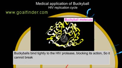
ave found potential uses in this world. For instance, doping a buckyball with potassium results in a superconductor that is functional at temperatures of 18 K, which a high temperature for a superconductor. Moreover, there’s evidence to show that buckyballs can bind to the insides of the protein HIV protease, effectively inhibiting their function and not allowing the HIV virus to replicate. And they may be even useful antioxidants. Buckyballs have a tendency to act as an electron reservoir; they can give free radicals (molecules specifically desiring an electron to become stable) the extra needed electron in order to stop them from taking electrons from other molecules inside the body. Plus, C60 is known to not be toxic to human cells, and it has the ability to go inside of cells rather easily. In fact, there’s olive oil with buckyballs dissolved in it at a concentration of 45 mg/50 mL on the market.

You Might Want to Duck

 http://www.rsc.org/images/buckyball-250_tcm18-187164.jpg

Even when leaving the confines of Earth, buckyballs were from its discovery speculated to exist in interstellar space, specifically because it has the ability to form in some of the mostadverse conditions known to exist. One theory about its formation is that UV irradiation takes PAHs (polycyclic aromatic hydrocarbons) and converts them to graphene and then into buckyballs. This is seemingly more efficient than an alternate explanation, one in which carbon atoms clump together in the hot, dense center region of stars.

The first place that buckyballs were found in (along with hydrogen) were planetary nebulae. Three nebulae with dying stars like ours contained these buckyballs; what makes this remarkable is that these stars were in our own galaxy. (Even more so, there was a nearby star containing buckyballs in a mass of nearly 15 times larger than that of our own moon). Nebulae are emitted by dying stars; in the middle of all the layers of gas being shed there is a white dwarf holding it all together. There is a stage where the white dwarf spits out a lot of carbon. Even more astounding was the hydrogen it was found with: researchers had previously assumed that the presence of hydrogen would cause it to form the chains and rings originally sought after. And that was just in the gaseous form: in 2012 it was found in solid form. What that means is not yet clear, but it can imply that it might have been a building block of life.

You’re probably sitting there shaking your head. So what if a molecule’s been found in space? It probably isn’t of much importance, is it? All these claims are surely false. Wrong. Buckyballs have been found in meteorites. Meteors, being the huge hunks of rock they are, have the ability to house materials not seen and never before seen on a planet. When they become meteorites and slam into Earth, not only does the resulting collision cause adverse climate changes (which no organism really likes, as evidenced by mass extinctions usually brought along with them) but it can also spread those materials all over Earth.

As stated at the beginning, a buckyball can hit a stainless steel plate at 15,000 mph and just bounce back, and it can also house atoms or even molecules inside. For instance, there was anasteroid impact marking the end of the Permian period, which took out nearly all life on Earth. The meteorite has been found to contain buckyballs housing helium-3 and helium-4, with helium-3 now being present in the atmosphere.http://www2.warwick.ac.uk/fac/sci/physics/research/condensedmatt/imr_cdt/students/kelvin_goh/endofullerenes/h2oc60/h2oc60_html_m71ddaf4.png?maxWidth=292&maxHeight=239

“Buckyballs are carbon molecules in the shape of a cage and they are very tough and hard to destroy,” said Kris Sellgren, a professor of astronomy at The Ohio State University in Columbus, OH.  She noted that although life forms, let alone a single molecule of DNA, absolutely dwarf a buckyball, “single atoms or small molecules can become trapped and can survive inside the cage while the buckyball safely travels through the harsh conditions of space.”

“Buckyballs with extraterrestrial gases trapped inside them, for example, have previously been found in meteorites that have slammed into Earth. Spotting buckyballs in interstellar space also reveals that relatively big molecules can persist and maybe even form in the diffuse, unforgiving voids between the stars.” These are something your regular soccer balls can’t handle.

Chemistry of Flow Batteries

Technology is progressing more and more with each passing day. In order to support these changes, advancements regarding power supply must also be made. At the moment, the trend is moving towards more efficient and sustainable sources of energy. The rechargeable, low-cost, and long-lasting flow battery seems to fit the bill perfectly. Of course, it is not as well known as the common lithium-ion battery because it is used on a larger scale rather than for small everyday items. It can be used to store excess electrical grid power which is then released during periods of high demand.

When you hear the word “battery”, the first thing that comes to mind is probably a package of AA or AAA batteries — you know, the ones with the adorable Energizer bunny on the front? Flow batteries are neither portable nor small. In fact, they consist of two liquid-filled tanks that are separated from the actual cell of the battery. These “tanks”, or electrolyte reservoirs, pump liquid electrolytes into two half cells separated by a membrane, as can be seen in the image below.

A reduction reaction takes place on one side and an oxidation reaction in the other, similar to the reactions within the fuel cells we mentioned in our last post. The membrane between the two half cells  keeps  the electrolytes separate, but is thin enough to allow certain ions to pass through in order to complete the redox reaction. Ions from both sides flow through the membrane and react with the electrodes on both sides of the cell, drawing energy from them. To store more power, the batteries can be stacked in a bipolar arrangement. At this point, they essentially provide unlimited electrical storage capacity. The only limit is the capacity of the electrolyte reservoirs.

Sounds pretty simple, right? Now for the interesting, and slightly more complex, part: how the actual energy storage takes place. The liquid electrolytes that flow through the cell are mixed with energy storing materials such as iron, vanadium, zinc, or bromine. Zinc-bromine flow batteries, for example, have a zinc anode in one half cell and a bromine cathode in the other. Aqueous zinc bromide is circulated through the two half cells. In discharge, (bottom image on right) a load is applied to the cell and the zinc metal on the anode is oxidized (Zn(s)↔ Zn2+(aq) + 2e) to form zinc ions and bromine is reduced to bromide ions at the cathode (Br2(aq)+ 2e ↔ 2Br(aq)). When the battery is completely discharged, the metal zinc on the anode dissolves in the electrolyte. It is stored there until the battery is recharged (top image on right), during which the reactions involving zinc and bromine are reversed. The zinc ions are reduced back to metal (Zn2+(aq) + 2e– ↔ Zn(s)), thus plating metallic zinc back onto the electrode. On the cathode side, bromide ions are oxidized into molecular bromine in the aqueous solution (2Br(aq) ↔ Br2(aq) + 2e) which combines with an oil to form a dense, oily liquid called a polybromide complex. As more polybromide complex is created and more zinc metal is plated onto the anode, the energy stored in the system increases. Because there are always fresh electrolytes in both half cells, the system is always ready to produce full power, even when the pumps are off. The electrodes in the zinc-bromine batteries don’t take part in thereactions but rather function as substrates, so repeated cycling won’t cause the electrode materials to deteriorate, as it would in most other rechargeable batteries.

So far, flow batteries seem like the best option available. The only problem is that they’re not quite available — not commercially, at least. Right now, the main issue is cost. The most commercially developed flow battery utilizes the rather expensive metal vanadium. For this reason, a team of Harvard researchers have recently developed a new type of metal-free flow battery that instead uses organic molecules called quinones, specially those found in rhubarb. According to Harvard author Roy Gordon, there is a limited number of metal ions that can be put into solution and used to store energy, none of which can store large amounts of renewable energy. For this reason, researchers have turned to organic molecules. The quinone used by the Harvard team is known as 9,10-anthraquinone-2,7-disulfonic acid (AQDS). What is unique about AQDS is its capacity for rapid reactions. It is able to undergo quick and reversible two-electron two-proton reduction on a glass-like carbon electrode in sulfuric acid. Although the small battery prototype has only run through about a hundred cycles, so far it has exhibited little to no losses. The model displays nearly the same performance as vanadium flow battery, but is much less expensive.

Flow batteries have a promising future, though they are not widely available at the moment and there are still unresolved issues regarding cost and production. Eventually, large quantities of energy will need to be stored and conserved in order to sustain our population and the great demand for power. Flow batteries will undoubtedly provide the best and most efficient solution.

Problems Arise: Balloons are Inflating the Helium Shortage


              It sounds ridiculous to think that something used everyday in birthday parties is in a serious shortage, but helium, an element used in applications ranging from balloons to MRI scanners, is now getting very difficult to find.  That means that very soon, your cousin may have a very disappointing birthday party. Yet that is the least of our problems.

              The most surprising thing about this shortage is that helium is the second most abundant element in our universe.  However, most of this helium is, practically speaking, way out of our reach.  Let’s embark on an exploration of helium to see why it is so hard to find, what Helium does for us, and what we can do in the future to make the search for it a little easier.

              The main trouble that arises when trying to obtain helium is that it’s less dense than air. This means that any helium trapped under the Earth’s surface eventually diffuses into the atmosphere. Once it’s in the air, it’s out of reach; we have yet to create a feasible means of collecting all of this diffused helium.  Currently, a huge build-up of Helium-4 (He-4) is being released in Yellowstone and about 60 tons of helium are released every year.  Some of this helium is diluted into the atmosphere, but the rest of it escapes the atmosphere into space.  Although it seems like we are letting this helium go to waste, there is just simply no viable way to collect it.

                                                                   yellowstone He.jpg                                                                                                                                                   
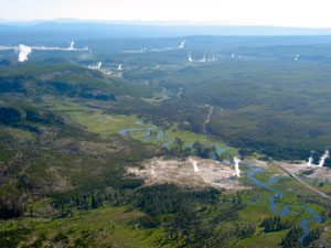
Yellowstone National Park

              Yet there are other factors that contribute to Helium’s shortage. For one, the production of Helium as a by-product of nuclear decay is not a heavily invested means of production. This is largely because it is not an economically viable option (along with capturing the diffused Helium in the air as mentioned before); however as we will see, the value of Helium just may be priceless.  Another factor contributing to the shortage is the fact that in the past few decades, the demand and use of Helium has skyrocketed, largely ascribed to our squandering ways. With a limited amount, prices of Helium have soared as well.

              So why exactly is helium important anyway?  Helium has a multitude of applications, but its main application is its use to cool superconducting magnets in MRI (magnetic resonance imaging) scanners. Superconducting magnets are magnets that can produce immense magnetic fields, which MRI scanners require to operate and use to construct images of the body. MRIs use superconducting magnets because below a certain temperature, known as a critical temperature, a metal loses its resistance (The reason this happens at low temperatures is because there are lower energy and less frequent atomic collisions). This temperature needed for superconductivity requires cryogenic temperatures.  That’s where helium comes in.  Liquid helium, due to its extremely low (4.2 K) boiling point and high thermal conductivity, is very efficient at capturing heat and is the only medium that can induce superconductivity in metal alloys. In MRI scanners, the wires are bathed in liquid helium at -269.1 °C to capture heat and remove it from the system. This effectively removes the wires’ resistance and allows them to become superconductors. However, a normal MRI scanner uses 1,700 liters of helium which periodically has to be changed. This is a huge amount of helium, especially with the impending shortage. A new method of superconductor cooling was recently developed by a company known as Cryogenic. This method uses a significantly lower amount of helium and may soon significantly reduce the amounts of helium that we waste.

                                                                 MRI.jpg

                                                                                 MRI Scanner

              Another important application of helium is its use in oxygen tanks for underwater diving.  Normally air is comprised of approximately 20% oxygen gas and 80% nitrogen gas. Nitrogen gas is a lot more soluble than Helium, and is especially soluble at high pressures – which essentially keeps the gases in solution. The difference in solubility between the two plays a key role in why Helium is used, and is due to their difference in size. In order to dissolve any substance into a solvent, the solute and solvent must have interactions with one another. For non-polar gases like N2 and He, it becomes difficult to create the interactions with polar water molecules. To actually bring one of these gases into solution, an induced dipole must be created in the gas. An induced dipole becomes increasingly easier as the molar mass of the substance increases. This is because there are then more electrons to shift between the atoms thereby creating a strong bond between the solute and solvent. Between N2 and He, nitrogen gas clearly dominates in molar mass and strength of LDF forces. So at these high pressures below the water, the nitrogen gas becomes highly soluble in the bloodstream inducing nitrogen narcosis, a state with similar effects to those of alcohol. Furthermore, as divers begin to rise from the water, the solubility of nitrogen decreases and begin to bubble out of solution (the blood). This is extremely dangerous as it can create bubbles in the bloodstream which wouldn’t be able to pass through fine capillaries in the body. The condition, called the Bends, is life threatening. To prevent this from happening, Helium is used. As stated previously, Helium is less soluble than Nitrogen, so less Helium would get into the bloodstream. Furthermore, Helium is an inert gas, so its narcotic properties are negligible and do not pose any problems of toxicity like Nitrogen does. Helium continues to be the most ideal gas for diving tanks, and the shortage poses a serious threat to the maritime industries.

              With such versatility it seems more likely that the United States will take on currently, non-viable means to produce Helium rather than drastically cut down on usage. There will likely be 3 primary sources that will serve the United States in the future as a source of Helium. As stated before the first source would be through nuclear reactions.  One reaction that results in a formation of a helium atom is plutonium decomposition (Pu-239).  A plutonium nucleus decays into an alpha particle and a uranium nucleus.  The alpha particle immediately captures 2 electrons from the nearby plutonium metal and becomes a helium atom in the midst of a plutonium lattice.  There are 2 main problems with this method of producing helium.  Firstly, this process has a half-life of 24,100 years.  Using the half-life formula for first-order reactions, one could calculate k to be (ln2)/t1/2 = (ln2)/24,100= 2.88 x 10⁻⁵.  Using the first-order integrated rate law, one could determine that in a year, 10,000 g of plutonium will decompose to 10,000 x e-2.88×10^-5 = 9,999.71 g.  Therefore, in a year, 10,000 g of plutonium will only decompose to 0.29 g of decay.  That’s a measly 0.0029% decay after an entire year.  This makes generating a profitable amount of helium unfeasible to say the least.  The second problem with this method is that once the helium is produced, it is stuck in the plutonium lattice.  This makes it become very difficult to isolate and extract

              The second source is actually through natural gas. Some natural gas contains amounts of Helium that can be extracted through a complicated process. The reason it is not widely used today is because the extraction process requires strict criteria and many samples of natural gas only contain about 0.3-1.9 percent Helium by volume. Furthermore, there are many economic considerations before uptaking such a project as the extraction process requires facilities. However, in essence there are 3 steps to the extraction process. The first step is to remove the impurities from the natural gas such as water, carbon dioxide and hydrogen sulfide through means such as amine and glycol adsorption. The second step is to extract the high molecular-weight hydrocarbons. Finally, through cryogenic processing the remaining methane gas is extracted. This works because Helium has the lowest freezing point of any element. So as the temperature is sufficiently reduced, all other substances will freeze and can be filtered out. What’s left is crude Helium, containing approximately 50-70% Helium and the rest is Nitrogen gas and other traces of gases. To further purify the Helium to approximately 99.99% purity, Pressure-Swing Adsorption (PSA) is used. PSA separates different gases from each other based on the premise that each gas has a different affinity for different adsorbent materials, and have different vapor pressures. Due to the varying vapor pressures, one gas can be completely transformed into the gas phase at one temperature and pressure and then extracted, while the other gas would remain largely as a liquid.

                                        adsorption.png                                                                                                     Pressure Swing Absorption Process

              The final source will actually be where Helium is most abundant: outer space. Observations from lunar missions have concluded that there are about 22 grams of helium in every cubic meter of lunar soil. In the future, if Helium were to ever run dry on Earth, this alternative would likely create a madman’s dash to the Moon in search of this precious yet scarce gas.

              In essence, our lavish uses of Helium without a steady state of supply has caused a shortage that affects many scientific disciplines that rely on the unique characteristics of Helium. As a human race, we must either cut down on our uses of Helium in some shape or form, or begin taking measures to create more Helium for use in the future. Without Helium, many of the opportunities and technology today will float adrift tomorrow, just an arm’s length away from humanity’s struggling grasp for the resources we use so plentifully.

Instruments and Chemistry: Rosin

 In the previous post, we talked about how certain chemicals have properties that allow them to be suitable for maintaining certain instruments. For this last post, we will further explore maintenance, as well as the chemistry behind certain chemicals since they are both complex and vital. Out of the chemicals that are used, rosin is the most complex since it is comprised of various organic and inorganic compounds. The following image shows how complex rosin can be, as well as showing how it is manufactured from the resin found inside trees. The central column only shows two possibilities that the four isomers can undergo since two molecules can be formed by simply arranging one of the bonds next to the additional Hydrogen.

Nigs.gif

          As one can see, the structure of the original organic compound varies by the location of the two double bonds, causing different concentrations of different acids to be present. These isomeric resin acids belong to the category of tricyclic diterpenes, whose basic structures result from the coupling of four C5-isoprene units (isoprene = 2-methyl-1,3-butadiene). The resin acids are distilled through 20% volatile turpentine and then leave behind some of the needed colophony rosin. However, some non-volatile alcohols and keto compounds are left behind and leave the molecule less pure and stable, so the compounds must undergo steam distillation in order to rearrange the atoms. Mechanistically, the rearrangement entails protonation at a terminal carbon atom of the conjugated double bond system, leading to a resonance-stabilized carbocation. The latter, through proton-transfer to the neighboring (allylic) CH2-group generates a rearranged diene, an unsaturated hydrocarbon with two carbon double bonds. The product ratio in the resulting equilibrium mixture is determined by the relative stabilities of the different conjugated dienes, and the stability gives the rosin the favorable properties that were mentioned in the previous post. While the acids in the final product are more concentrated, they are more stable and pure due to the addition and relocation of the Hydrogen atoms. The original resin is only 72% pure, while the final rosin is 95% pure; the rest of the percentages are non-volatile solids that hinder the rosin’s physical properties. This is why the levopimaric acid is the only substance that becomes less concentrated: it is the least volatile acid out of the four main acids that appear, and it slightly lessens the quality of the rosin as a whole. However, it is needed since the durability of the rosin can be attributed to this acid in particular.

          One of the most important chemicals used in the production of a piano is called lacquer.  Lacquer is more or less a wood polish; it is the chemical added to wood to give it the smooth and shiny properties.  Without it, the wood of a piano would be a lot more difficult to work with, shrinking the lifespan of the common piano by years if not decades.  Without lacquer, the piano and other hammered string instruments may have never become the influential instruments they are today.  But what exactly is lacquer?

          Lacquer is a polymer of many different bases that when coated on a wooden substance, offers a layer of protection and gloss to a piece of wood. The most common lacquer used on piano frames is a urushiol-based lacquer. Urushiol is a common allergen found in many Anacardiaceae plants such as poison ivy.  It has a boiling point of
200˚ C (392˚ F) and can dissolve in substances such as alcohol.  It is composed of a 6 carbon ring with 3 double bonds similar to benzene, 2 hydroxyl groups, and an R group. The R group varies from a large amount of hydrocarbons (such as (CH2)14CH3, (CH2)7CH=CH(CH2)5CH3, (CH2)7CH=CHCH2CH=CH(CH2)2CH3and others).  While harmful to many humans on poisonous plants, urushiol offers a special breed of polymer that can be used as piano frame lacquer.  It is a special type of lacquer in the sense that it settles in a more elaborate and controlled way. While most lacquers dry solely by evaporation, urushiol-based lacquers will oxidize with the air surrounding it and undergo polymerization.  This requires the settling process to be in a humid and warm environment, to avoid any evaporation.  However, if done properly, this lacquer will offer a completely optimized layer of shiny aesthetics and protective lifespan to the frame and other wooden pieces of a piano.

          As mentioned in the string section of our last blog, the best cleaning agents for brass instruments tend to be Trichloroethylene (TRI) and Perchloroethylene (PERC).  Last time, we talked about greases and oils for brass instruments, but sometimes build-ups of these compounds can form in sludge-like globules inside our instruments.  For degreasing and all-purpose cleaning, TRI and PERC are excellent reagents.  These compounds are heavy, maintain constant pH while cleaning, and dissolves quickly due to high solvency. It should also be noted that without adding stabilizing factors, these compounds are rather unstable and can react violently with metals, especially those made from Aluminum and/or Magnesium. These stabilizing factors are also able to protect Aluminum against decomposing.  In addition, more recently ultrasonic cleaning of instruments has been used instead of the degreasers.  This method takes advantage of a phenomenon called ultrasonic cavitation.  When water (or another liquid) is bombarded with the correct ultrasonic frequencies, very small bubbles form causing agitation. This extreme agitation can loosen contaminants sticking to a metal surface.  Adding certain ions to the water can greatly increase the rate of the reaction by reacting spontaneously with the contaminants with the added energy from agitation.  Finally, in the case that you would need to remove the lacquer from your brass instrument, acetone will work well.

The Manufacturing Processes of OLEDs

At the recent CES convention in Las Vegas, many new products were unveiled and demonstrated.  Both the public and professional communities were captivated by the new OLED technologies.  However, as the prices were announced, it soon became clear to the techno-savvy consumers at home that it would be many years before OLEDs were a common sight in the average household.  Although the prices seemed daunting, the manufacturing methods used to produce these organic screens have been steadily improving.  As a revolutionary advance in display technology, OLED displays are expected to overtake the LCD market in the near future.  Thus, many researchers have worked tirelessly to develop a more efficient and quicker method in order to make OLEDs a more accessible technology.

Patternable OLEDs operate through a light or heat activated electroactive layer.  This is a polymer that exhibits a physical change when stimulated with an electric field.  A popular polymer for this layer is PEDOT-TMA, which becomes a highly efficiently hole injection layer.  It is a p-type conducting polymer and a modification of the PEDOT monomer, which is based off the EDOT monomer and can be seen below.  PEDOT-TMA is a popular material for this layer because it is noncorrosive and dispersible in organic solvents.  This is due to the methacrylate groups at both ends of the polymer chain.  These caps limit the length of the polymer, making it more soluble in organic solvents and ideal for usage in OLEDs.  These OLEDs are conventionally produced through the use of two main patterning technologies, organic vapor phase deposition (OVPD) and inkjet etching (IJE).

The PEDOT-TMA chain.  The two methacrylate caps at the end are clearly visible.

Organic Vapor Phase Deposition 

The organic vapor phase deposition manufacturing process works by transporting organic molecules to a cold substrate through the use of a hot inert carrier gas.  The final film product can be fine-tuned by altering the gas flow rate and source temperature.  Uniform films are produced by lessening the carrier gas pressure, which creates a larger velocity and mean free path of the gas.  This leads a decrease in the thickness of the boundary layer.  OVPD is also popular for OLED production because the process naturally prevents issues related to contaminants from the walls of the chamber.  This is because the walls are naturally warm, which prevents molecules from sticking to and producing a film.

However, maintaining a uniform film thickness and dopant concentrations over the large surface area needed for many applications is a demanding task in the context of vacuum evaporation, which is currently the most prevalent method of depositing organic molecular solids.   In addition, there is a relatively low yield with OVPD production, which explains the massive production costs.  As a remedy, low pressure organic vapor phase deposition has been proposed as a substitute technique.  This process has a notably improves command over doping and offers a potential method to rapid, particle-free, uniform deposition of organics on large-area substrates.  Further information detailing the uses and advantages of OVPD can be found here.

Inkjet Etching

The most basic method of producing OLEDs incorporates old technology originating from 1976, when the first inkjet printer was created.  Inkjet printing is a cheap and efficient alternative to traditional OLED production and is used by several start-up OLED companies such as Kateeva.

The Kateeva system for inkjet etching.

Kateeva’s system of inkjet printing involves a movable platform capable of holding screen substrates of up to 55” diagonal length.  The movable platform is able to transfer a selected substrate under various print heads, which are then able to spray droplets of organic material from different nozzles.  These drops of organic material are placed precisely (picoliter scale) on a selected substrate to form the pixels on the screen.  Additionally, the inkjet printing system is a versatile procedure, as it can be adapted from large television screens to small handheld devices such as smartphones and tablets.

This process is not as accurate or efficient without the use of a shadow mask on the substrate.

Shadow mask used for consistency and quality of the final display.

A shadow mask is a fine metal stencil drawn on the substrate that directs the material spray into its correct place, ensuring the consistency and quality of the final screen.  However usage of the shadow mask, while convenient and economical, also has its downfalls.  The shadow mask may lead to contamination of the organic materials of the OLED screen.  Because the OLED screen is composed of organic products, it is extremely sensitive to outside particles that may cause a drop in the vibrant image quality.  Nevertheless, inkjet printing is still a viable method for producing OLED displays and further improvements will reduce the risks of contamination.

New Developments in the OLED Industry

Recently, researchers have discovered that utilizing a molecule of a certain shape and structure allows anew type of OLED that has the potential to emit as much light as a commercial OLED, but without the need for costly rare metals normally demanded to make the OLEDs effective. Rare earth metals such as iridium or platinum are currently vital to OLED displays because it increases the efficiently of the display to commercial standards.  The removal of these expensive metals from the production of OLEDs has the potential to significantly reduce the costs of OLEDs.  This improvement in OLED structure is vital to advance the technology and reduce prices as the OLED industry of smartphones, televisions, and solid-state lighting continues to grow.

New developments regarding OLED production also includes metal oxide deposition systems.  These have potential to become leading production methods because they are more efficient and consistent in their output than the currently costly production methods.  For example, the AKT-55KS, a plasma enhanced chemical vapor deposition (PECVD) system that handles 8.5-Gen substrates, is a good option to consider based on its defect-free nature and its ability to keep out unwanted gases.

AKS-55KS

Two systems that hold potential for widespread use is the new physical vapor deposition (PVD) deposition systems, which comes in 2 models: SKT PiVot 25K which controls Gen-6 substrates, and the SKT PiVot 55K which controls 8.5-gen substrates.  The advantages of these systems are derived from the utilization of tubular cathodes of donor material, where the cathodes rotate because of the process of deposition.

Conclusion

Constant innovation is a necessity of a demanding market, especially in an industry that is still attempting to establish itself as a viable consumer market.  The production of OLEDs is still in its infancy, as there are several obvious and monumental obstacles that present itself in the first phases of starting such a market.  The most pressing issue is the costly and inefficient manner in which these organic LED’s are created, which has prompted researchers to find ways to reduce these expenses. This had led to the introduction of the inkjet printer formatted specifically for the production of OLEds as well as the new deposition systems offer viable alternatives that hold promise for a market that contains endless possibilities. One can only speculate the boundless paths that the OLED industry can take, whether it be into solid-state lighting, a lucrative smartphone market, or both.  Consumers can only wait to see what the raw potential of this revolutionary technology can manifest into.